Vickers | KDG4V-3S-2C08S-M-FW-H5-60
KDG4V-3S-2C08S-M-FW-H5-60
Request a Quote
What Happens Next?
Email Confirmation
You will get an email confirming we have received your inquiry.
Dedicated Account Manager
A team member will review your request and be in touch concerning any questions or specifications.
Quote Delivered
You will receive a comprehensive quote tailored to your specific needs.
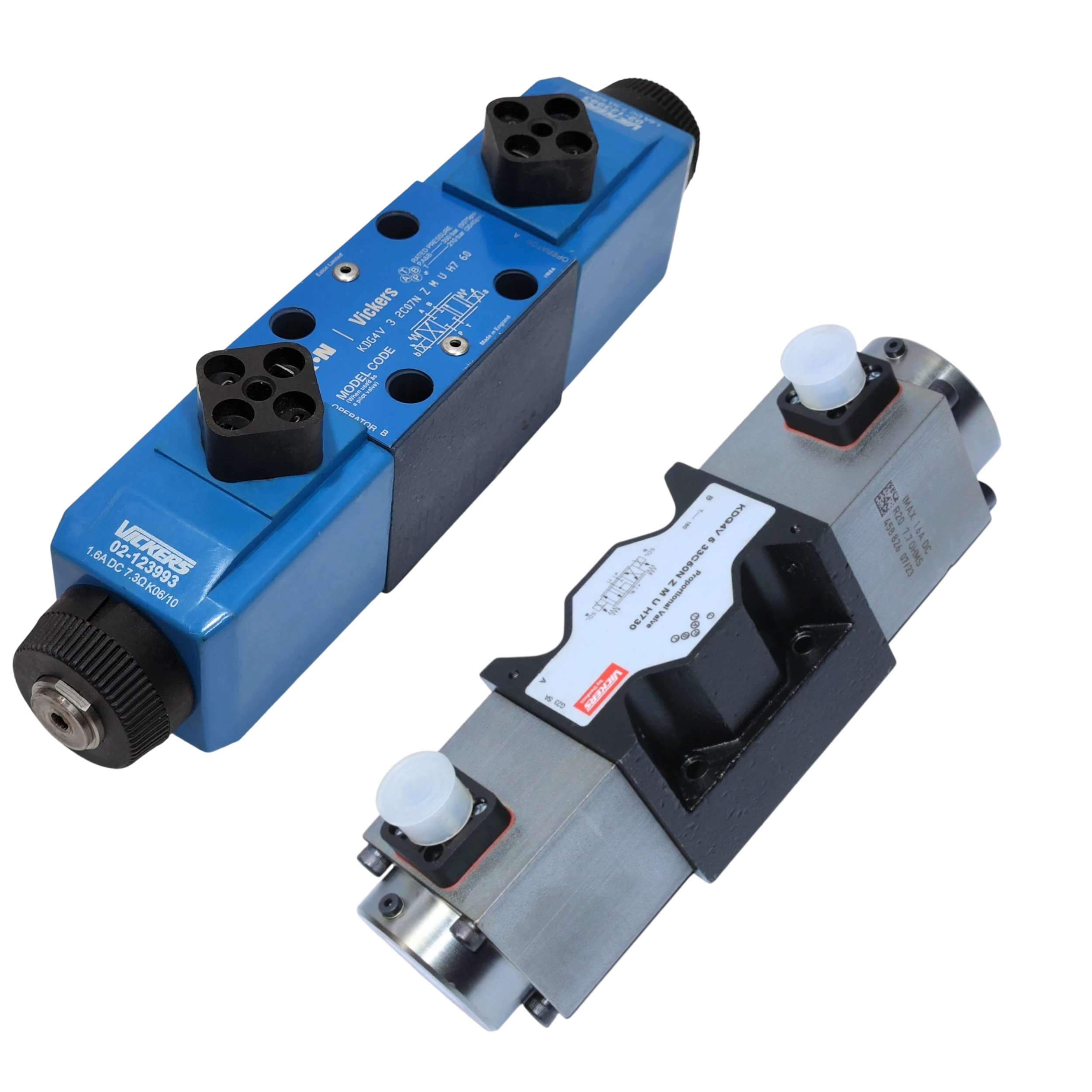
The KDG4V-3S-2C08S-M-FW-H5-60 proportional valve belongs to the KDG Non-feedback Proportional Valves series manufactured by Vickers for hydraulic automation where an electrical command positions the spool without internal feedback. It directs oil through a looped flow path (P→A/B plus B/A→T) so both work ports receive supply and return channels simultaneously during actuation. An ISO 4401-AB-03-4-A mounting pattern lets the unit bolt directly onto NFPA D03 subplates used on compact manifolds. Mounting surface flatness of 0.013 mm limits distortion that could create internal leakage between pressure zones, and a surface roughness of 1.1 µm supports proper gasket sealing. The assembly withstands 350 bar (5000 psi) on pressure, service, and pump lines, while the tank line can carry 100 bar (1450 psi) of back-pressure without affecting spool motion. A −3 dB frequency response of 18 Hz defines the bandwidth available for following rapidly changing electrical signals. The step response from 0 to 100 percent command is completed in 100 ms, and the return from 100 to 0 percent takes 15 ms, ensuring predictable cylinder acceleration and deceleration. Repeatability of 1 percent keeps identical commands producing the same flow rate from cycle to cycle.
The electromagnetic section contains a coil with 29 mH inductance at 1 kHz. This inductance moderates current ripple produced by PWM drive circuits and helps stabilize spool motion. Coil resistance measured at 20 °C is 7.3 ohm, and this resistance works with the inductance to define the electrical time constant that influences driver tuning. A maximum coil current of 1.6 A at 50 °C sets the thermal ceiling for continuous actuation. At nominal room temperature the coil draws 18 W, a load that must be included in cabinet power budgets. Hysteresis under PWM control stays within 4 percent, limiting flow error when commands reverse direction. Electrical entry is provided through an NPT threaded port that accepts standard conduit fittings for sealed wiring. Together these figures guide amplifier settings and wiring choices when integrating the valve into hydraulic manifolds.
Technical Specifications
Coil Inductance (h @1 Khz)
29 mH
Coil Resistance (h @20 C)
7.3 Ohm
Electrical Entry Thread
NPT
Flow Path
Looped (P→A/B plus B/A→T)
Frequency Response (−3 Db)
18 Hz
Hysteresis With Pwm
4%
Max Coil Current (h @50 C)
1.6 A
Max Operating Pressure (a/b/p)
350 bar (5000 psi)
Max Tank Line Pressure (t)
100 bar (1450 psi)
Mounting Pattern
ISO 4401-AB-03-4-A (NFPA D03)
Mounting Surface Flatness
0.013 mm
Mounting Surface Roughness
1.1 µm
Power Consumption @ 20 C
18 W
Repeatability
1%
Step Response 0–100%
100 ms
Step Response 100–0%
15 ms
Shipping & Payment Options