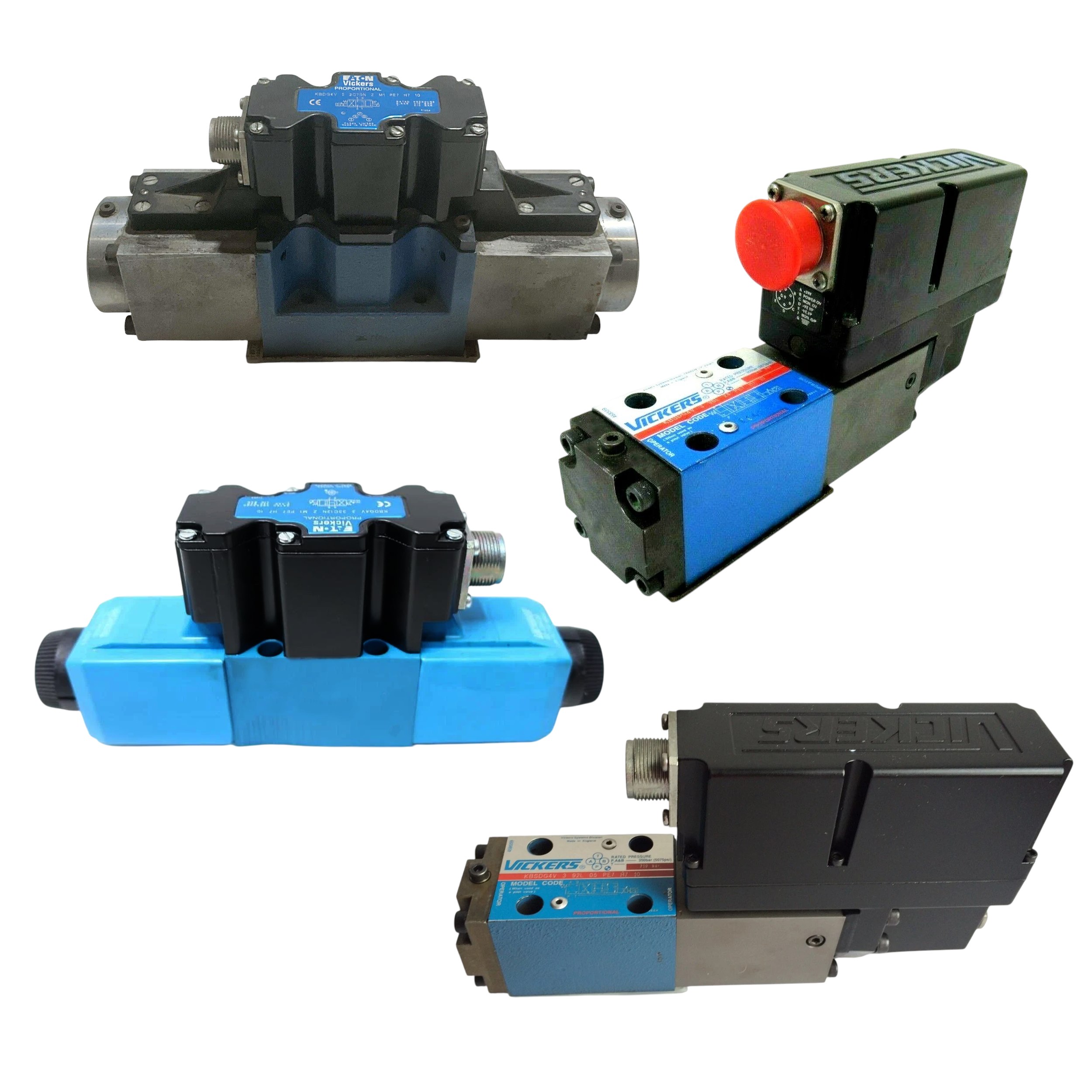
Vickers | KBDG5V-7-2C180N-M1-PE7-H1-10
KBDG5V-7-2C180N-M1-PE7-H1-10
Request a Quote
What Happens Next?
Email Confirmation
You will get an email confirming we have received your inquiry.
Dedicated Account Manager
A team member will review your request and be in touch concerning any questions or specifications.
Quote Delivered
You will receive a comprehensive quote tailored to your specific needs.
The KBDG5V-7-2C180N-M1-PE7-H1-10 valve belongs to the Directional Control Valves series manufactured by Vickers for closed-loop hydraulic automation. It accepts a ±10 V DC command so motion controllers can drive the spool proportionally, and the electronics operate from a 24 V DC supply delivered to pin A while pin B provides the 0 V reference; supply ripple may reach 10 percent peak-to-peak without affecting response. The internal amplifier starts responding once the input exceeds a 0.25 V threshold, and it modulates the solenoids at a 10 kHz PWM frequency to maintain precise metering. A monitor output on pin F mirrors the command with a ±10 V DC signal for diagnostics, and common-mode voltage relative to pin B is limited to 18 V to protect the circuitry. Because the PE7 version leaves pin C unconnected, no external enable signal is required; the unit is active whenever power is present. Drive leads on pins D and E furnish the positive and negative actuator voltages, and total supply current remains within 3 A. Differential voltage between pins E and D is kept below 100 mV so that null drift is minimized during steady operation.
Hydraulically, the valve routes flow between ports while tolerating demanding system pressures. The P, A, and B work ports can handle as much as 350 bar when an external drain is provided, whereas the T return line is rated for 210 bar with an internal drain path, and the Y case-drain port shares the same 210 bar limit. During directional changes, the actuator chambers receive oil from the control end volumes; 7.28 cm³ is displaced from the center position to either end, and 14.56 cm³ is exchanged when stroking completely from one end to the opposite end. These defined volumes allow motion controllers to calculate fill times and damping rates accurately. The stated pinout—A for 24 V, B for 0 V, F for feedback, G for protective earth, plus the drive outputs on D and E—supports straightforward wiring in manifolds or sub-plates that integrate multiple axes. Together, the electrical and hydraulic characteristics make this valve suitable for precise, high-pressure positioning tasks in presses, injection machines, and other automated equipment.
Technical Specifications
Command Signal (m1)
±10 V DC
Common Mode Voltage To Pin B
18 V (Max)
Control Volume Center-to-end
7.28 cm3
Control Volume End-to-end
14.56 cm3
Enable Input (pin C)
Not Connected (PE7)
Max Differential E-to-d
100 mV
Max Port Pressure P/a/b (ext Drain)
350 bar
Max Port Pressure T (int Drain)
210 bar
Max Port Pressure Y
210 bar
Max Supply Current
3 A
Monitor Output (pin F)
±10 V DC
Pinout (7-pin)
A +24V, B 0V, D +V, E -V, F ±10V, G PE
Pwm Frequency
10 kHz
Supply Ripple (max)
10% p-p
Supply Voltage
24 V DC
Threshold Command Voltage
0.25 V
Shipping & Payment Options