Vickers | RG06A230
RG06A230
Request a Quote
What Happens Next?
Email Confirmation
You will get an email confirming we have received your inquiry.
Dedicated Account Manager
A team member will review your request and be in touch concerning any questions or specifications.
Quote Delivered
You will receive a comprehensive quote tailored to your specific needs.
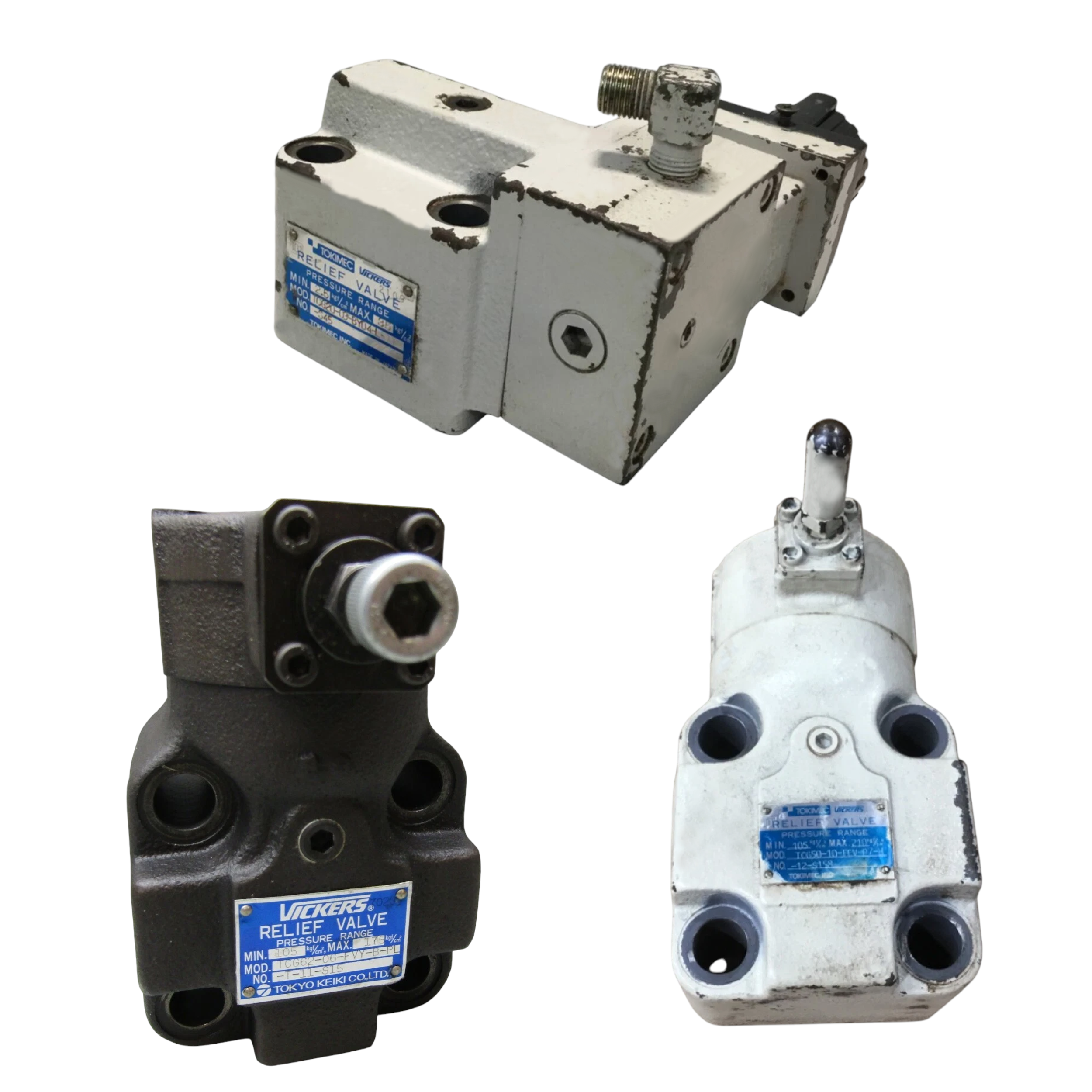
The RG06A230 relief valve belongs to the Relief Valves series and is produced by Vickers for hydraulic automation circuits that require predictable pressure sequencing. It is a direct acting unit, so the poppet responds to pressure without pilot stages to reduce reaction time. The valve performs a sequence function, allowing a secondary line to pressurize only after the primary circuit reaches its set point. A maximum working pressure of 210 bar (3000 psi) defines the ceiling at which the valve components remain structurally sound, while the minimum relief margin of 17 bar (250 psi) establishes the differential between cracking and reseat pressure for stable cycling. Flow can reach 114 l/min (30 USgpm), supporting medium-capacity systems without excessive pressure drop. The capacity rating is based on oil at 20 cSt (100 SUS), so viscosity near this value maintains the stated flow performance. A rated fluid specific gravity of 0.865 is used for pressure calibration to keep setting accuracy consistent with typical petroleum oils. The nominal valve size is 3/4 in, matching common header dimensions and easing selection with standard manifold blocks.
The valve uses an external drain, identified as Type 2, to route leakage directly to tank and avoid back-pressure interference with the setting. Its interface conforms to NFPA P06, allowing bolt-on installation to standardized patterns. Mounting can be on a manifold or subplate, giving builders flexibility depending on block design. The mounting counterbore diameter is 15.1 mm (0.594 in), ensuring the body seats flush without rocking, and four bolt holes of 10.3 mm (0.406 in) diameter secure the housing and resist loosening under cyclic load. Primary gauge port threads are 7/16-20 UNF-2B so a pressure transducer or gauge can be attached upstream of the orifice, and an identical 7/16-20 UNF-2B thread is provided for the secondary gauge port to enable downstream pressure monitoring.
Technical Specifications
Drain Configuration
External Drain (Type 2)
Interface Standard
NFPA P06
Maximum Flow Capacity
114 l/min (30 USgpm)
Maximum Working Pressure
210 bar (3000 psi)
Minimum Relief Margin
17 bar (250 psi)
Mounting
Manifold or Subplate
Mounting Counterbore Diameter
15.1 mm (0.594 in)
Mounting Hole Diameter
10.3 mm (0.406 in)
Nominal Valve Size
3/4 in
Operation Type
Direct Acting
Primary Gauge Port Thread
7/16-20 UNF-2B
Rated Fluid Specific Gravity
0.865
Rated Viscosity For Capacity
20 cSt (100 SUS)
Secondary Gauge Port Thread
7/16-20 UNF-2B
Valve Function
Sequence
Shipping & Payment Options