Vickers | DG4V3S6CYMKUH560EN435B23
DG4V3S6CYMKUH560EN435B23
Request a Quote
What Happens Next?
Email Confirmation
You will get an email confirming we have received your inquiry.
Dedicated Account Manager
A team member will review your request and be in touch concerning any questions or specifications.
Quote Delivered
You will receive a comprehensive quote tailored to your specific needs.
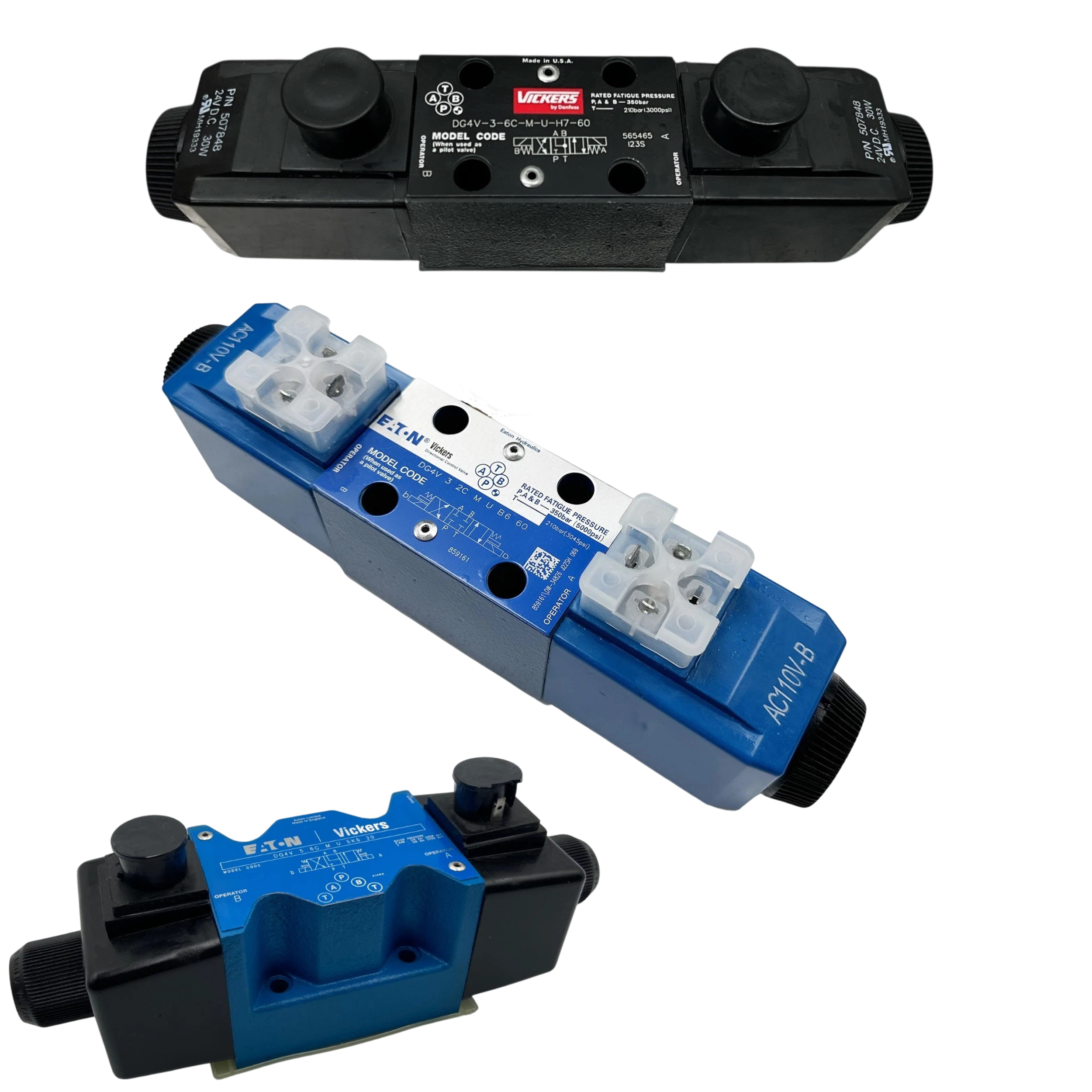
The DG4V3S6CYMKUH560EN435B23 valve belongs to the DG4 Directional Valves series produced by Vickers for hydraulic automation systems that require electrically shifted flow paths. It uses a spring-centered spool that automatically returns to neutral when the solenoid is de-energized, preserving actuator position without operator input. The spool is a closed center design that blocks the pressure port while connecting A and B to tank; this arrangement isolates the pump and relieves actuator lines during standby. A rated flow of 40 l/min (10.5 US gpm) defines the maximum volume that can pass through the valve at nominal conditions, and port P, A, and B can withstand pressures up to 350 bar (5000 psi). The tank port tolerates 100 bar (1450 psi) so return line backpressure remains within safe limits. An ISO 4401-03 (CETOP 3) mounting interface with an NFPA D03 port pattern enables direct installation on standardized subplates and manifolds used in compact power units.
The electrical section is built around a 24 VDC solenoid rated at 30 W, letting the valve integrate with typical machine control supplies while limiting current draw. Coil insulation is Class H, and the encapsulation is Class F, a combination that protects the windings and maintains thermal endurance during continuous service. Because the duty cycle is 100 % ED, the coil can stay energized indefinitely without exceeding temperature limits. Reliable actuation is maintained down to 90 % of the rated supply voltage, allowing operation during brief voltage dips. A top-exit flying-lead connection (KU) provides flexible routing when space above the manifold is restricted. A latching manual override is included so technicians can shift the spool mechanically for setup or in the event of power loss. The complete assembly weighs 2.2 kg, information needed when sizing mounting studs or assessing load on manifold brackets.
Technical Specifications
Coil Encapsulation
Class F
Coil Insulation
Class H
Coil Power
30 W
Coil Voltage
24 VDC
Duty Cycle
100% ED
Electrical Connection
Top Exit Flying Leads (KU)
Manual Override
Latching Type
Max Pressure (p, A, B)
350 bar (5000 psi)
Minimum Supply Voltage
90% rated
Mounting Interface
ISO 4401-03 (CETOP 3)
Port Pattern
NFPA D03
Rated Flow
40 l/min (10.5 US gpm)
Spool Arrangement
Spring Centered
Spool Type
Closed Center (P blocked; A&B to T)
Tank Port Rating
100 bar (1450 psi)
Valve Weight
2.2 kg
Shipping & Payment Options