Vickers | DG4V-3S-6C-M-KUP5-D2-G5-EN202
DG4V-3S-6C-M-KUP5-D2-G5-EN202
Request a Quote
What Happens Next?
Email Confirmation
You will get an email confirming we have received your inquiry.
Dedicated Account Manager
A team member will review your request and be in touch concerning any questions or specifications.
Quote Delivered
You will receive a comprehensive quote tailored to your specific needs.
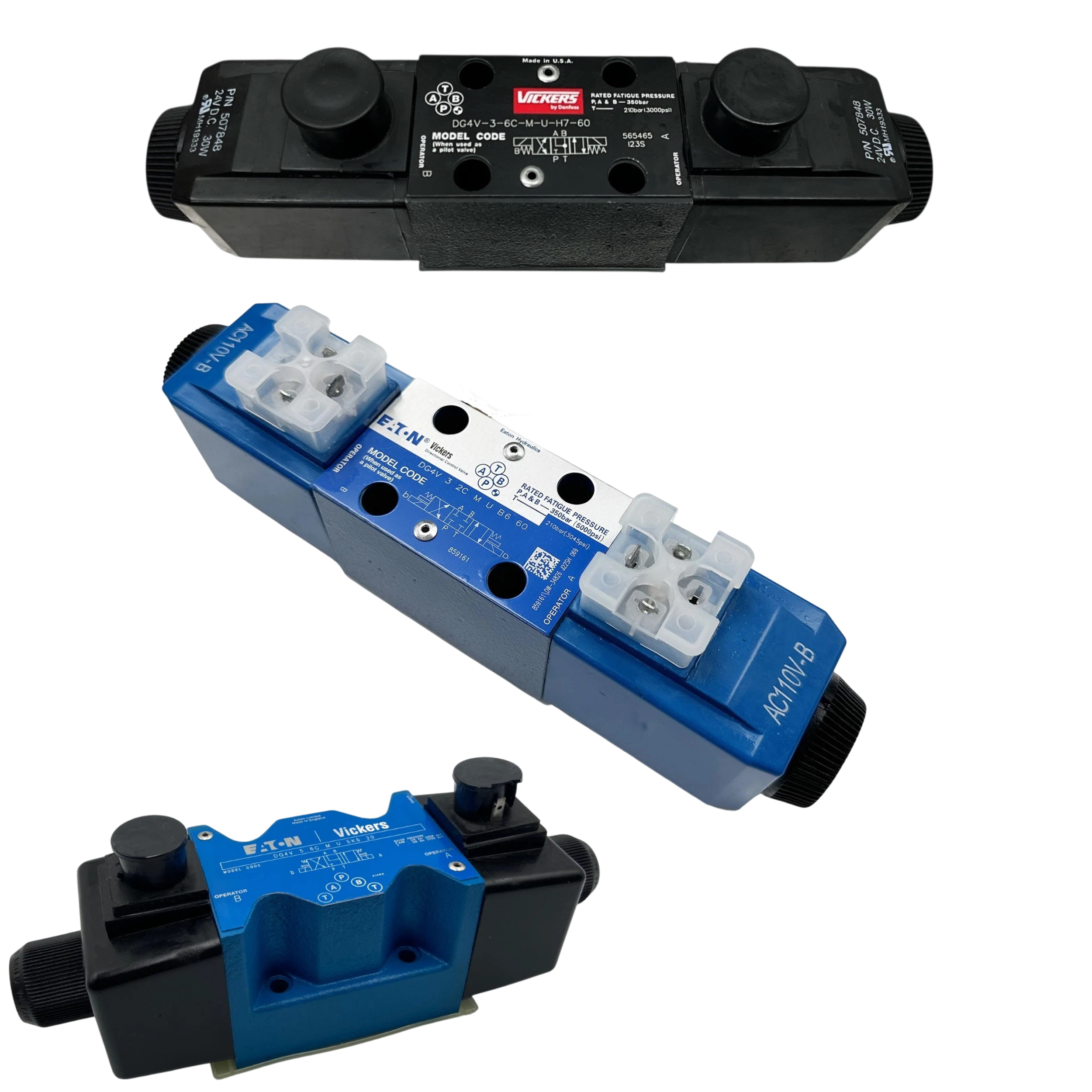
The DG4V-3S-6C-M-KUP5-D2-G5-EN202 valve belongs to the DG4 Directional Valves series produced by Vickers for use in hydraulic automation systems where on-command flow paths must shift rapidly and reliably. It sustains port pressures up to 350 bar (5000 psi) on p, A, and B, making it suitable for high-pressure actuator lines, while the tank port tolerates 210 bar (3000 psi) so return circuits remain protected. Continuous duty operation (ED 100 %) lets the coil stay energized without forced cooling, and the dc coil draws 30 W, which eases power supply sizing. Electrical reliability is supported by Class F coil encapsulation that wards off moisture and vibration, plus Class H winding insulation that withstands elevated temperatures. A minimum supply voltage of 90 % of rated prevents erratic spool movement during voltage dips. Surge suppression is handled by a diode labeled D2 to limit back-EMF, and when fitted with the correct connector the assembly reaches IP67 ingress protection for temporary immersion tolerance.
Clean system fluid is essential, so inlet filtration must meet ISO 4406 19/17/14 to curb spool wear and sticking. Installation uses M5-0.8 or #10-24 UNC-2B mounting threads that match common manifold plates, and bolts graded Class 12.9 or better clamp the body securely under full service pressure. The mounting face must hold a flatness of 0.013 mm to avoid internal leakage paths, while a surface roughness of 1.1 µm ensures the seals seat correctly. A 4.00 mm (0.157 in) locating pin hole provides precise alignment for repeatable servicing. Designers should leave 50.0 mm clearance to nearby components so the coil can be removed without obstruction and airflow is not restricted. These mechanical and cleanliness requirements combine with the electrical and pressure ratings described earlier to support dependable shift performance in automated hydraulic circuits.
Technical Specifications
Coil Encapsulation
Class F
Coil Winding Insulation
Class H
Duty Cycle
Continuous (ED 100%)
Filtration Requirement
ISO 4406 19/17/14
Ingress Protection
IP67 (depending on connector)
Locating Pin Hole
4.00 mm (0.157 in)
Max Port Pressure (p, A, B)
350 bar (5000 psi)
Max Tank Pressure (t)
210 bar (3000 psi)
Min Spacing To Obstructions
50.0 mm
Minimum Supply Voltage
90% of rated
Mounting Bolt Grade
Class 12.9 or better
Mounting Thread
M5–0.8 (#10-24 UNC–2B)
Power Consumption (dc Coil)
30 W
Surface Flatness (mounting)
0.013 mm
Surface Roughness (mounting)
1.1 µm
Surge Suppression
Diode (D2)
Shipping & Payment Options