Bosch Rexroth | 4WEH32Q6X6EW110N9EK4B08
4WEH32Q6X/6EW110N9EK4/B08
Request a Quote
What Happens Next?
Email Confirmation
You will get an email confirming we have received your inquiry.
Dedicated Account Manager
A team member will review your request and be in touch concerning any questions or specifications.
Quote Delivered
You will receive a comprehensive quote tailored to your specific needs.
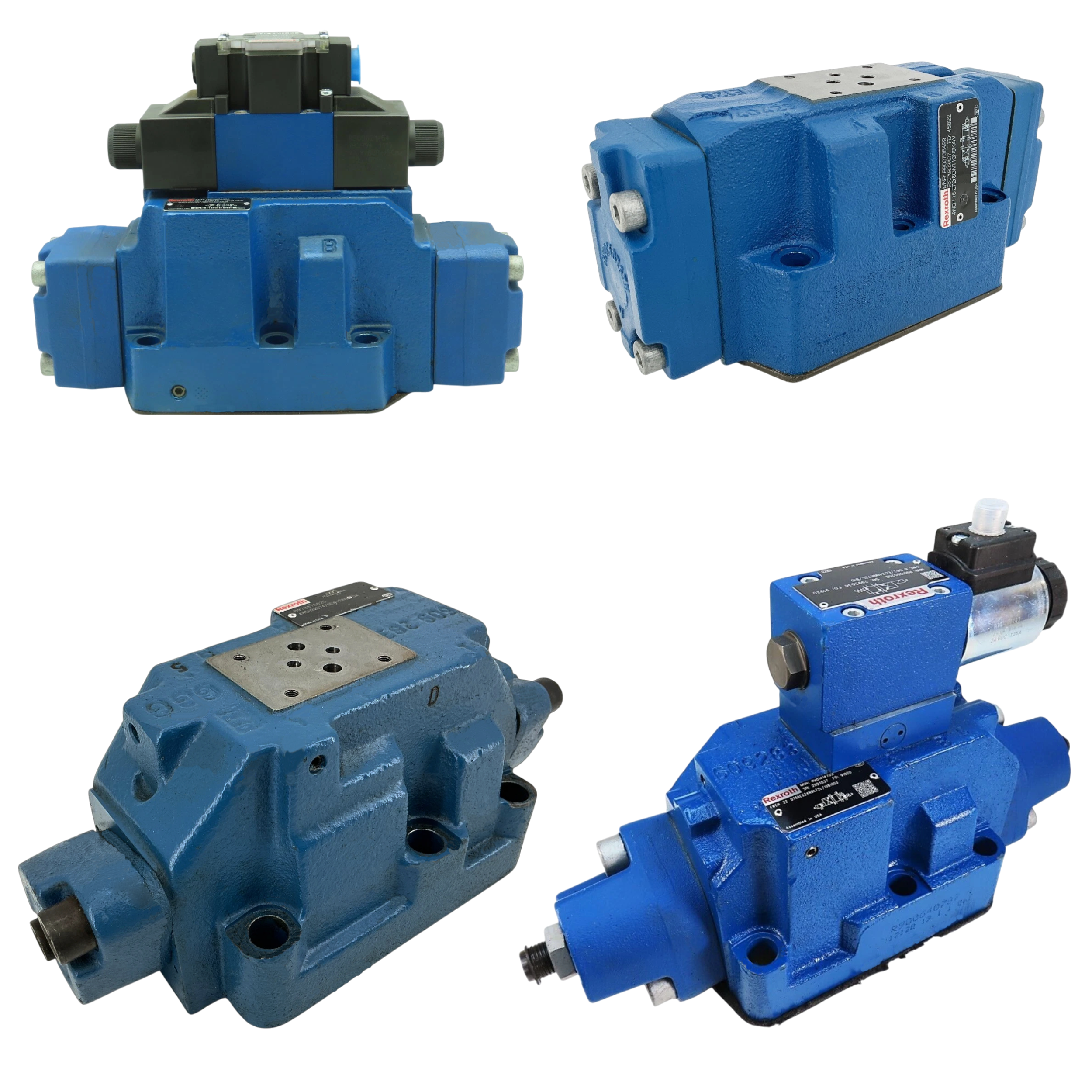
The 4WEH32Q6X/6EW110N9EK4/B08 directional spool valve belongs to the WEH Directional Spool Valves series and is produced by Bosch Rexroth. It directs pressurized fluid to selected work ports in hydraulic automation circuits. Electro-hydraulic actuation uses a pilot stage to shift the main spool without large solenoid forces, supporting smooth transitions. The NG32 nominal size defines port diameters large enough for high system flow rates. Its mounting face follows ISO 4401-10-09-0-05, so the valve fits standard subplates in machinery. The spool has three spring-centered positions, returning to neutral when pilot pressure is removed. Pilot oil is taken internally and returned externally, reducing leakage into the tank line. Electrical connection is made through a DIN EN 175301-803 K4 plug, allowing quick coil replacement. A concealed manual override labeled N9 lets maintenance staff shift the spool mechanically without energizing the coil. The pilot stage operates once 8.5 bar is available, guaranteeing reliable switching at low system pressure. A 0.8 mm throttle insert in the B08 variant restricts pilot flow to dampen actuation speed and limit shock.
At 350 bar the valve passes up to 680 l/min, while its unrestricted channel supports a maximum flow of 1100 l/min when pressure drop is acceptable, enabling large actuator speeds. Working ports P, A, and B tolerate 280 bar, maintaining sealing integrity under common industrial pressures. The tank port T is rated for 250 bar so it can be connected to accumulator circuits that run above atmospheric pressure. External drain port Y withstands 160 bar, preventing case pressure buildup when the return line sees elevated levels. The maximum pilot pressure of 250 bar keeps the control stage within safe structural limits during high-pressure cycles. In neutral, a free flow area of 78 mm² across A–T and B–T paths minimizes heat generation by allowing oil to circulate with low resistance. These hydraulic limits, together with the flow capacities stated earlier, define the operating envelope for the valve. This balance between pressure capability and free flow area keeps energy loss manageable during standby periods.
Technical Specifications
Actuation
Electro-Hydraulic
Electrical Connection
DIN EN 175301-803 (K4)
Manual Override
Concealed (N9)
Max Flow Q (350 Bar)
680 l/min
Max Operating Pressure (p,a,b)
280 bar
Max Pressure Port T
250 bar
Max Pressure Port Y (external, Ac)
160 bar
Maximum Flow
1100 l/min
Maximum Pilot Pressure
250 bar
Minimum Pilot Pressure
8.5 bar
Nominal Size
32 (NG32)
Pilot Oil Configuration
Internal Supply, External Return
Porting Pattern
ISO 4401-10-09-0-05
Spool Positions
3 (Spring-Centered)
Throttle Insert Orifice
0.8 mm (B08)
Zero-pos Free Flow (q, A–t/b–t)
78 mm²
Shipping & Payment Options